
INTEGRATION / PLC · DAQ · PANEL METER
Draw-wire sensor wiring & commissioning guide
Compare a two-wire current loop, three-wire voltage transmitter and passive string potentiometer before selecting the receiving input.
These diagrams show circuit functions. Use the released sensor and controller manuals for terminal numbers, wire colors, supply ratings and grounding.
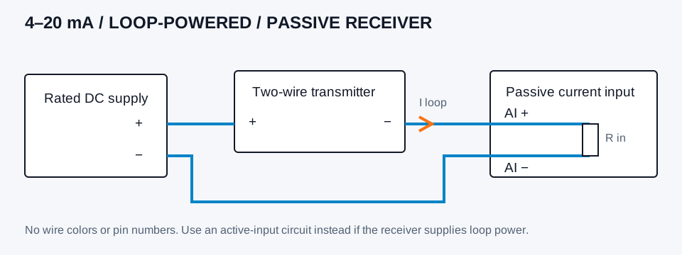
Two-wire 4–20 mA: supply the loop once.
This example uses a loop-powered transmitter, a separate DC supply and a passive current input. Current flows through the transmitter and receiver in series. Check whether your PLC input already provides loop power before using this circuit. Do not add a second loop supply to an active, loop-powering input; follow that input card’s circuit instead.
V supply ≥ V transmitter minimum + I maximum × (R input + R cable) + other series voltage drops
Use the supply tolerance and the maximum expected loop current, including diagnostic overrange if specified. Illustrative nominal-span check: a 24 V supply, a transmitter needing 10 V and a 250 Ω receiver leave 9 V for cable and other drops at 20 mA. This arithmetic does not approve a particular transmitter or fault-current condition.
Verify current-input mode, burden, polarity, isolation and channel common restrictions. A three-wire current transmitter needs its own specified supply/common/output circuit. Do not substitute a voltage-input terminal without a correctly sized and rated shunt arrangement.
Three-wire 0–10 V: reference the signal correctly.
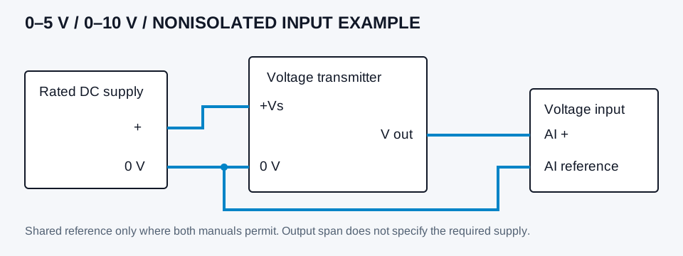
Match 0–5 V or 0–10 V to the actual input range, impedance and common-mode limits. Supply voltage is a separate specification from output span. In this nonisolated example the sensor common and receiver reference share 0 V; check the permitted grounding arrangement before joining commons. Route the signal away from motor power cables and terminate shields according to the equipment manuals. An isolated input can also measure this output when connected to the appropriate signal reference under its own input specification. Ground potential differences between cabinets can cause current in a shared reference conductor and measurement error. Review isolation and grounding where that risk exists; a differential input alone does not provide galvanic isolation.
String potentiometer: measure a voltage ratio.
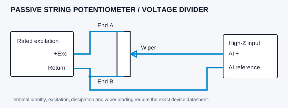
The resistive track has two end terminals and a moving wiper. With negligible loading, V wiper / V excitation follows the calibrated fraction of stroke. Track utilization and endpoint offsets may prevent the output from reaching exactly 0% and 100% of excitation; use the supplied transfer function.
A low receiver impedance loads the divider and changes the transfer curve. Check excitation dissipation (P = V²/R), maximum excitation and wiper-current limits together. Use a suitable high-impedance input or buffer. A passive divider is not a powered 0–10 V transmitter, and resistance alone does not establish a permissible excitation voltage. Identify the wiper before applying power; do not tie it directly to a supply rail.
Illustrative loading check: an ideal 10 kΩ track at midstroke has 5 kΩ above and below the wiper. A 100 kΩ receiver across the lower half changes its equivalent resistance to about 4.762 kΩ and the output ratio from 0.5000 to 0.4878. That is a 1.22% excitation-span deviation at this point, before other errors. Choose input impedance from the allowed loading error and actual track utilization, rather than a universal resistance rule.
ABZ and absolute buses need different commissioning data.
Incremental A / B / Z
Match driver levels and receiver type: HTL, TTL and differential line-driver inputs are not interchangeable by name alone. Confirm complementary channels, supply, shield and cable-length limits from both device manuals.
Document the A-channel cycle count and PLC decoding multiplier. Move a known distance, check sign and count scale, then test the reference strategy after power loss. An index Z pulse is a reference event, not an absolute multi-turn position.
Absolute position
Confirm single-turn and multi-turn capacity, output units, update rate and overflow behavior. Test the actual device’s position retention and motion while unpowered, where relevant.
Request the matching register map for RS485/Modbus, EDS for CANopen, PGN/SPN definition for J1939, bit/timing definition for SSI, GSDML for PROFINET or ESI for EtherCAT. Check availability and version for the quoted hardware.
Commission in a controlled sequence.
- Read the configuration documents. Identify exact sensor, connector, output, power and PLC/readout input type. Isolate power and machine movement before connecting.
- Set the mechanical travel. Align the cable exit, reserve travel at both ends, and check the full motion path without exceeding the specified measuring range. Guide the cable back by hand during installation.
- Verify the electrical channel. Check polarity, supply at the sensor, input mode and grounding. Confirm a plausible zero signal before moving the target.
- Scale against independent positions. Record zero, intermediate points and full-scale indication using a suitable independent length reference. Repeat in extension and retraction.
- Test the actual operating sequence. Check speed, restart, signal loss and readout alarms with hazardous motion inhibited under the machine’s commissioning procedure.
Stop if the cable rubs, crosses itself, loses tension or the output saturates. A guide pulley must have an approved bend radius, alignment and groove for the cable; an extension cable does not increase calibrated sensor stroke.
Technical sources and document scope
Reviewed November 3, 2026. These original manufacturer references support the engineering principles. Their specifications apply to their own products; a selected DWP configuration needs its own released drawing and specifications.
- SICK: scaling a wire-draw encoder — Drum travel per revolution and position scaling.
- US Digital: resolution terminology — Native encoder cycles and quadrature decoding; naming conventions vary.
- NI: 4–20 mA loop fundamentals — Loop supply, receiver burden and wiring voltage loss.
- Micro-Epsilon: WPS K100 setup guide — Manufacturer installation precautions and example output variants.
- TE Connectivity: SP2-50 — Original 50-inch string potentiometer with voltage-divider output.