
PLC / DAQ / ENCODER INPUTS
Draw-wire sensor output selection
Choose the receiving signal, define the position reference after power loss, and prepare an interface request. Then check pulse frequency and the documents needed for integration.
START WITH THE CONTROLLER INPUT
Which signal can the receiving channel accept?
Select a signal to see its circuit or protocol checks and the documentation to request. If the input is unknown, include the controller and input-card part number in your enquiry.
Request an input-card review ↗A signal label leaves four integration questions open.
- Does the receiving channel accept the specified circuit and electrical driver?
- Are scaling, update rate and position representation defined?
- Can the machine recover a valid position after the stated power-loss conditions?
- Are the drawing, device file and instructions for the actual hardware revision available?
The selector lists requested interface routes. A listed signal or family is not a released configuration, an approved replacement or evidence of stock.
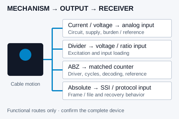
| Requested signal route | Receiving channel | Decision that the name does not settle |
|---|---|---|
| 4–20 mA / two-wire | Appropriate loop current input | Active/passive input, loop supply, compliance and burden. |
| 4–20 mA / three-wire | Current input for the specified powered output circuit | Supply/common/output wiring and sourcing/sinking behavior. |
| 0–5 V / 0–10 V | Matching voltage input | Supply, signal reference, impedance, common-mode limits and isolation. |
| 1 / 5 / 10 kΩ divider | Suitable high-impedance voltage or ratio measurement | Excitation, track utilization and receiver loading error. |
| Incremental ABZ | Suitable high-speed counter | Driver levels, cycle-frequency rating, decoding and reference strategy. |
| Absolute SSI / network request | Matching SSI master or protocol-capable controller | Frame/message format, device description, startup validity and multi-turn behavior. |
Use the functional wiring guide for current-loop, voltage and divider circuits. A PLC brand name, a connector shape or the presence of Ethernet/CAN hardware does not establish protocol support.
ABZ / IDEAL INPUT-FREQUENCY BUDGET
25 kHz on A can produce 100,000 decoded counts per second.
The editable example uses 200 mm of cable travel per encoder revolution, 5,000 A-channel cycles/rev, ×4 decoding and 1 m/s peak cable speed.
No receiver limit entered. Check its rating and whether it refers to channel cycles or decoded counts.
Use cable travel per encoder shaft turn, not drum diameter. Enter native A-channel cycles before quadrature decoding and the peak speed rather than average stroke/time.
fA = (speed × 1,000 / travel per revolution) × cycles/rev. Decoded rate = fA × decoding. Count size = travel per revolution / (cycles/rev × decoding). Use effective travel at the encoder shaft, including gearing; do not multiply an already decoded count specification by four again.
This ideal constant-scale calculation does not validate driver levels, input filters, simultaneous-channel limits, cable effects, mechanism dynamics or accuracy. Use the rated input basis and allow for the actual operating conditions; equal-to-limit arithmetic is not a qualification.
View calculation text for manual copy
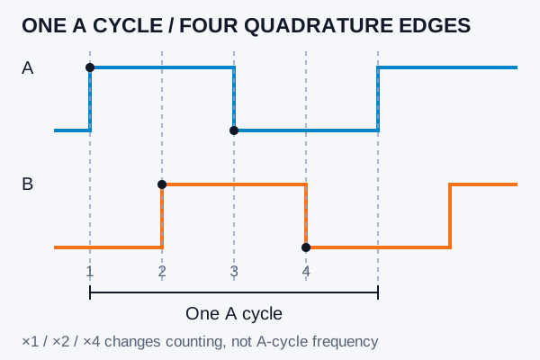
Apply ×4 to decoded events, not to the physical A-cycle rate.
Here PPR means A-channel cycles per encoder revolution. Manufacturer terminology varies: a number called CPR or PPR may already describe decoded counts. Confirm its definition before applying a multiplier.
A controller can specify a maximum channel frequency, a maximum decoded rate, or additional restrictions. Use the stated rating basis and the allowed filter/channel mode. The calculator only compares the numerical basis you choose.
NI encoder frequency and decoding reference. Count size is a nominal increment, distinct from linearity and system accuracy.
| Rate being compared | Calculated requirement | Arithmetic result |
|---|---|---|
| A-channel cycles / second | 25,000 Hz | Below an entered 32,000 Hz channel-cycle limit. |
| Decoded events / second at ×4 | 100,000 counts/s | Above an entered 32,000 decoded-counts/s limit. |
| Equal to a rated limit | No nominal numerical allowance | Do not interpret equality as complete hardware qualification. |
PROTOCOL ≠ CONNECTOR ≠ DEVICE FILE
Request the description for the exact protocol and revision.
A device file helps the controller interpret a specific device. It does not establish the mechanical travel, error, power-loss behavior or interchangeability of a draw-wire mechanism.
| Interface request | Documents / parameters to confirm | Primary reference |
|---|---|---|
| RS485 / Modbus RTU | Register map, function codes, baud/parity/address and multi-register ordering | Modbus specifications |
| CANopen | CANopen EDS/DCF, object dictionary and PDO mapping for the actual revision | CiA 306 file formats |
| SSI | Bit allocation, binary/Gray code, clock/pause timing, error/status bits and connector | RLS SSI explanation |
| J1939 | PGN/SPN or manufacturer-specific payload definition, scaling, address and timing | SAE vehicle application layer |
| PROFINET | Matching GSDML, module/submodule layout, process-data definition and update limits | PI GSD / GSDML library |
| PROFIBUS DP | Matching PROFIBUS GSD, module/data layout and bus settings | PI GSD / GSDML library |
| EtherCAT | Matching ESI, PDO/process data, state behavior and supported synchronization | Beckhoff ESI notes |
| EtherNet/IP | EtherNet/IP EDS, I/O assemblies, connection parameters and update limits | ODVA developer resources |
RS485 does not define a register map.
Confirm whether the chosen device uses Modbus RTU, then obtain the position registers, function codes, units, signedness and multi-register byte/word order. Do not assume a universal address or a universal A/B terminal designation.
CANopen, J1939 and Ethernet protocols stay distinct.
CANopen and J1939 use different application definitions. PROFINET, EtherCAT and EtherNet/IP are different integration routes. An EDS for one protocol is not a substitute for an EDS of another protocol; PROFINET GSDML and PROFIBUS GSD are also distinct.
Advanced bus interfaces are configuration requests requiring availability and document review. No EDS, GSDML, GSD, ESI, register map or performance rating is inferred from an enclosure photo or this comparison.
Power-up position and motion while unpowered are different requirements.
| Required behavior | What to establish |
|---|---|
| Reference can run after startup | Reference event, permitted travel, sign and scaling. Incremental counting still needs a validated reference strategy. |
| Position needed without startup homing | Whether the complete mechanism and controller recover a valid position, not just a retained displayed number. |
| Target may move while unpowered | Recovery of that motion, multi-turn capacity, overflow and any energy/battery-related conditions for the actual design. |
| Analog / divider readback | Whether the sensing core and scaling yield the intended position after power restoration, plus startup validity and receiving-channel conditions. |
A general “absolute” interface label is not a guarantee of unpowered multi-turn tracking. Conversely, an external retained counter/reference system may be part of a valid incremental installation; its behavior needs to be described and verified as a system.
Include the allowed reference motion and expected restart sequence. Check process alarms separately from the machine’s validated protection and travel-limit architecture.
THREE ILLUSTRATIVE REQUESTS / NO APPROVED MODEL IMPLIED
Turn the controller requirement into a reviewable enquiry.
1 m hydraulic analog retrofit
Assume a passive current input and a requested two-wire transmitter. Select 4–20 mA, then provide the supply, burden and cable route. A matching current span does not settle loop compliance or mounting.
Open this analog example ↗Incremental high-speed input
Assume HTL is the documented receiver requirement. The calculator example needs 25 kHz on A and produces 100,000 decoded counts/s at ×4. Confirm the receiver’s rated basis and how the axis references at startup.
Open this incremental example ↗Gate position over CANopen
Assume CANopen is required and the gate may move while unpowered. Request the device EDS/process data and whole-device position-recovery evidence. CANopen by itself does not answer the recovery question.
Open this absolute-interface example ↗Close the interface questions before fixing the order code.
- Identify the receiving controller and input-card part number.
- Define travel, cable motion, output representation and startup/reference behavior.
- Confirm the quoted model, electrical circuit and available protocol variant.
- Confirm whether the interface is native or uses a gateway/conversion unit, including its power, mounting and startup requirements. Review the exact wiring drawing, firmware/device file and scaling revision.
- Validate the complete measurement and restart sequence under the required conditions.
Engineering time, controller configuration, any interface hardware and required validation belong in the package review. An apparently lower sensor price does not settle integration cost.
Is RS485 the same as Modbus?
No. RS485 identifies an electrical interface. The device must explicitly support the required application protocol, register map and communication settings.
Can a CANopen encoder replace a J1939 sensor on the same wiring?
Do not infer that from the CAN connection. Confirm the application protocol, messages, device configuration and physical network requirements.
Does TTL always mean a differential RS422 counter input?
No. Confirm the actual driver and receiving circuit, signal levels, supply and complementary channels.
Does ×4 decoding multiply the A-channel waveform frequency?
It changes how many edges are counted. It does not change the A-channel cycle frequency generated at a given shaft speed and A-cycle resolution.
Can I compare decoded counts/s directly with a PLC input frequency in Hz?
Only after establishing what the PLC rating means. Use a common basis and the permitted filter/channel mode; some ratings have additional restrictions.
Does an absolute interface retain all movement through a power failure?
That depends on the complete sensing design, multi-turn capacity and controller behavior. State motion while unpowered as an explicit requirement.
Can I download a DWP device file from this comparison?
This page specifies which file to request. Availability and the matching hardware/firmware revision must be confirmed for the proposed configuration.
Which information reaches the enquiry from the selector?
The selected signal, optional travel/family scope and position-reference requirement are prefilled. Counter-calculator inputs stay in the calculator; use its copy button to paste the calculation into enquiry notes.
Engineering sources reviewed November 3, 2026. Standards and manufacturer references explain interface principles; their device ratings and files are not DWP specifications. Original diagrams and worked numbers are illustrative.