INDUSTRIAL LINEAR POSITION MEASUREMENT METRIC / INCH · ANALOG / DIGITAL
DWPLINEAR METROLOGY
Sensor seriesReplacement reviewAccuracy guideRequest quote / CAD ↗

DWP-POS / Analog position / PLC & DAQ

4–20 mA & 0–10 V Draw-Wire Position Sensors

Convert hydraulic cylinder stroke or machine travel into a scaled analog signal for a PLC or data acquisition system.
200–10,000 mm7.874–393.701 in
Configure your RFQ ↗
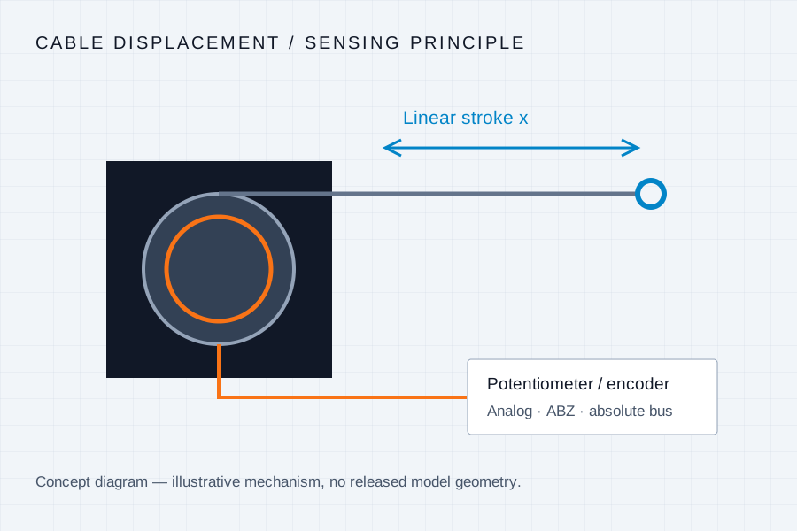
Cable extension turns a spring-return drum coupled to a potentiometer or encoder.
Measurement principle · concept illustration

STROKE × SIGNAL × LINEARITY

Confirm the measurement envelope.

Selection envelopes · model-specific confirmation required
ModelMeasuring stroke / mm & inchLinearity targetSignal outputWire rope optionComparison reference
DWP-POS200–10,000 mm
7.874–393.701 in
±0.15% FS target4–20 mA · 0–5 V · 0–10 VØ0.6–1.0 mm SS316 optionMicro-Epsilon MK88 / MK120; Celesco PT families; ASM

Family ranges are selection envelopes. Output availability, linearity, cable construction, drawings and delivery are confirmed for the quoted configuration.

Output choices require different electronics. A voltage divider, 4–20 mA loop and 0–10 V transmitter are separate configurations.

BEFORE THE MODEL IS FIXED

Four checks for DWP-POS integration.

Hydraulic cylinders, injection molding machines and mobile machinery require a sensor configuration matched to the actual machine and measurement task.

  1. 01Two-wire loop versus three-wire transmitter wiring
  2. 02Supply voltage, loop burden and input impedance
  3. 03Required zero / span mapping and overtravel allowance
  4. 04Cable exit direction, speed and environmental exposure
INSTALLATION NOTE / CONTROL THE RETURN

Never release an extended measuring cable.

Hold the cable end and guide retraction throughout installation. Free snapback can injure the installer and damage the cable, drum or sensing element. Keep the cable aligned with the outlet; use a suitable guide pulley for a change of direction.

Stroke, cycle rate, speed, acceleration, cable force and contamination determine service life. Request the specific model instructions and validated limits.

DWP-POS / QUOTATION + ACCESSORIES

Build the sensing package around your machine.

Request the model drawing, cable exit layout and proposed interface with your quotation. Accessory prices below are indicative planning additions, confirmed in the written quote.

Readout, routing & installation options

Indicative additions for quotation planning. Confirm compatibility and final price with the selected sensor.

Extension joints must stay outside the sensor outlet, wiper and pulley. An extension cable does not increase calibrated stroke. Panel relay outputs require machine-specific control validation.

DWP-POS

Send your measurement requirements

By submitting, you ask DWP to contact you about this request. Privacy policy. Email drawings to [email protected].

Related stroke and interface decisions

Resolution, linearity and repeatability ↗Review an existing part number ↗

DWP Linear Metrology

Every millimeter.
The right signal.

[email protected]

Choose your interface

DWP-ENC / Draw-Wire EncodersDWP-POS / 4–20 mA & 0–10 V Draw-Wire Position SensorsDWP-SP / Compact String Potentiometers & Wire PotsDWP-LNG / Long-Range Draw-Wire TransducersDWP-KIT / Draw-Wire Sensors with Digital Display

Engineering resources

Compare a replacementStroke, linearity & installationAbout DWPRequest drawings & quotation
© 2026 DWP Linear Metrology
PrivacyTermsCookies